RIM Molding Design Considerations
RIM Molding Design Guide
At Thieme, our RIM molding services include providing an efficient and dynamic molding service perfect for low annual volume requirements and unique part applications.
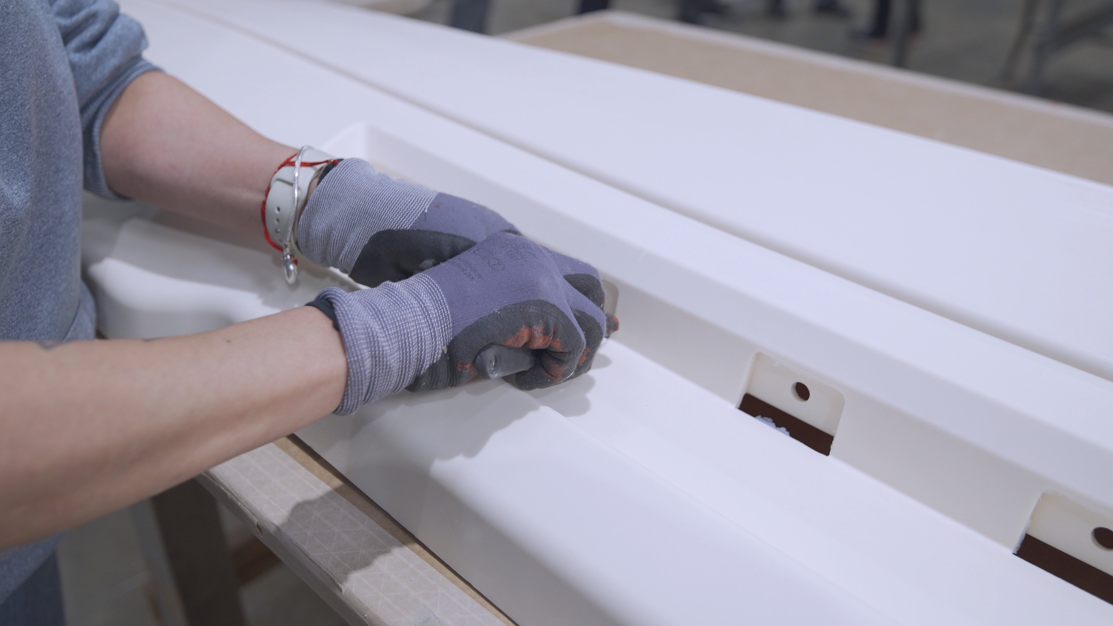
Our RIM molding design methods enable the part designer more freedom in the design as the process is not pressure and heat driven only. With RIM materials and process the designer can make large parts, parts with deep draws, parts with variable wall sections and parts with DFMA principals molded into the B-side of the part.
With the low molding temperatures, gravity fed liquid cavity fill and the foaming nature of the RIM processes, this enables less built in stresses and opens larger material paths for the part design.
The design of the molds must match some of the advantages and designing your wall sections, ribs, bosses, slots and other features must be done with the RIM process in mind.
For more RIM molding guidelines and design considerations, contact us below.


RIM Molding Design Considerations
Before you decide which molding technology you’ll use for your design project, you should consider the following:
- Material selection for part dimensional stability and part function
- How large of a part can I mold? With RIM it’s up to 8’ x 8’ x 2’
- Do you need to vary wall sections in the same part without sink or distortion?
- The ability of parts to retain shape, stability and quality over product life cycle
- Does the part geometry require deep draws?
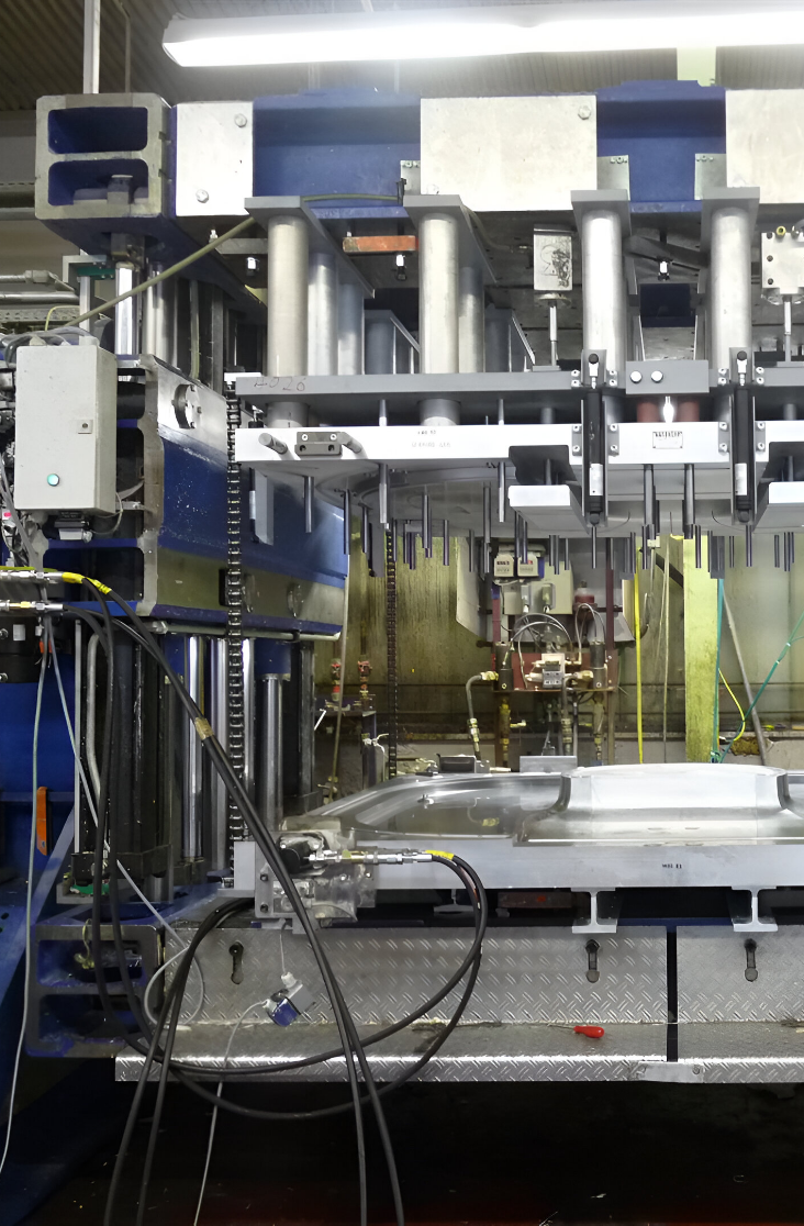
- RIM tools are aluminum and at Thieme, are guaranteed to last
- The costs of post-mold assembly using other technologies other than RIM
- The importance of easy to mold in features and inserts in your design
- The ability to incorporate bosses, ribs, wire guides, glue features without post mold operations?
- The ability to design features for both the A side of the parts and the B side of the part
With all this in mind, we have two RIM molding design considerations to choose from.
Functional considerations
Consider the environment in which you want your design to operate. Think about the temperature, humidity levels, stiffness levels, the degree of high impact resistance, conditions in which parts are loaded, attaching requirements, structural conditions, chemical resistance levels, the need for insert molding and use of a structural foam system.
- Environment the part will operate in
- UV
- Temperature
- Humidity
- Necessity for high impact resistance or stiffness
- Parts loading conditions, attaching requirements, structural conditions
- Chemical Resistance needed
- Is Insert molding needed
- Do you need a foamed system to cut down on part weight?
Economic considerations
While many think that weight matters most in economic design, it’s actually the net shape that’s vital. The RIM process allows you to cut down on the costs per volume.
You can also take a look at our RIM Molding design guides below to learn more about our recommendations. At Thieme we provide High Level Assembly and value-added operations. Our RIM molding technology can handle very large parts, multiple walled sections, deep draws and complex geometries
When making cost considerations, remember it’s the net shape of part that is important, not the weight. So make cost per volume calculation instead of cost per pound material decisions. Remember a 1” wall section in a foamed polyurethane will be much less than other materials systems including metals.
Look at the part geometry for load bearing applications.
Optimize wall thickness and rib ratios to reduce cost and weight.
Consider if the parts require paint.
Contact Thieme today to find out more about our RIM molding design guide.
When considering RIM molding technology for your next low volume plastic enclosure, housing or assembly, there are many things to consider including, part size, part function, value added assembly, design for assembly techniques, molding in features, part cost, post mold assembly costs, rim tooling investment, part quality, repeatability and the ability for the tools and parts to retain quality, function and dimensional stability throughout the entire lifetime of the series production. Our design considerations will assist you to do that.
General Part Design
Part Stiffness
- Balance wall thickness and flexural modulus
- Balance wall thickness and material density in foamed systems
- Improve stiffness by adding glass (where possible)
- Improve stiffness and reduce wall sections by using higher modulus systems, improving part geometry or adding reinforcements and encapsulations
Wall Thickness
- Thicker Walls have higher stiffness
- Double the wall thickness of a flat and the stiffness will increase by a factor of eight
- Wall thickness can range from 1/8” up to 2” depending on the material system used and geometry
- Thicker wall section require more cure time
- Watch abnormally thick walls as they can cause dimensional stability issues due to longer cooling.
Rib Design and Configuration
- Taller thinner ribs are more effective than shorter, wider ribs.
- Run ribs continuously from side to side.
- Design ribs in the direction of draw to minimize mold cost
Draft
- Every surface parallel to the direction of draw needs draft (1/2 a degree min) to facilitate demolding.
- As the part height increases over 1”, draft should increase.
- Add ¼” degree draft for each additional inch of draw over 1”.
Bosses
- Attach bosses to the side walls of the part to allow air to escape during the molding process
- Avoid isolated bosses
- When design bosses that are not attached to a side wall, use gussets or vent the boss with a core
- All bosses need radii at their bases
Undercuts
- If possible, avoid undercuts.
- Undercuts can be molded but may be costly and only possible in localized areas
Holes, Grooves and Slots
- Holes can be drilled in the part post mold, molded in the direction of draw or formed by a retractable pin using hydraulics in the tool.
- Holes in side wall are also possible having the core and cavity meet at the hole.
- Orient grooves and slots in the flow direction to minimize air entrapments.
- Make sure grooves and slots are rounded or chamfered rather than sharp to help flow and vent air.
- Consider positioning slots in a side wall curled around the base plane to allow for molding without slides.
Inserts
- Minimum distance for the insert to the part wall should be 1/8 “ for a solid PUR or ¼” for a foamed system.
- Metal, plastic, glass and electronics can be encapsulated in PUR materials
- Threaded Inserts can be used if the parts are to be frequently disassembled by the end-user.
- Threaded inserts can be either post mold or molded in the part
- The insert design, hole diameter, part density and screw size determine the pullout force and stripping torque of threaded inserts.

Send Us Your Project
Upload your CAD files (Pro-E, SolidWorks, STP or IGES) along with your annual volumes, paint requirements and other project specific information and we’ll prepare an estimate for the cost and timing for the RIM tooling and part costs of your project.